The solar spectrum changes throughout the day and with location. This is because of a combination of local atmospheric conditions and geometric considerations. The tropics, for example, receive more irradiance on average than the equator due to a lower prevalence of clouds, which reflect much of the incoming solar radiation (see Figure 1). This variation in the solar irradiance would make it extremely difficult to compare the performance of different solar cell technologies measured in different locations, even if you kept the time of day and year kept consistent. For this reason, it is necessary to have ‘standardised’ solar spectra. These spectra function as a universally accepted reference for testing and comparing photovoltaic devices.
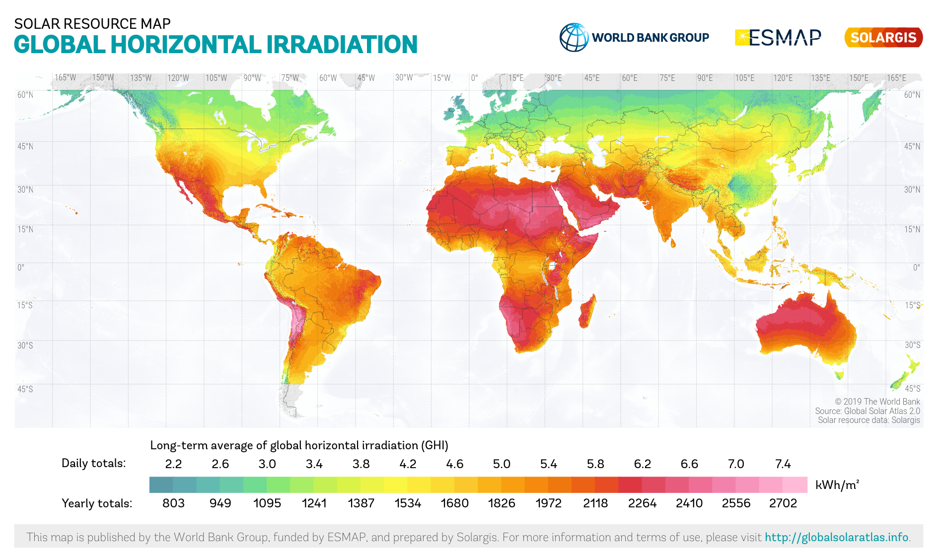
Figure 1. Map of long-term average of global horizonal irradiation
Standard reference spectra are defined to allow the performance comparison of photovoltaic devices from different manufacturers and research laboratories. The first standardised solar spectrum came from the International Commission on Illumination (CIE) in 1972 and represented the solar noon sun at the equator on an equinox ($θ_s = 0°$) with no cloud but a defined volume of water vapour, ozone and aerosols in the atmosphere. They also suggested using an irradiance of 1000 W/m$^2$ (100 mW/cm$^2$) in the 290 nm – 3000 nm wavelength range as a reference intensity. This reference spectrum has been refined over the years. In 1982 the American Society for Testing and Materials (ASTM) published two calculated reference spectra that would become the basis for standardised solar cell testing:
- A direct normal irradiance spectrum (AM1.5D)
- A global horizontal irradiance spectrum (AM1.5G)
The ‘AM1.5’ in both reference spectrums refers to the air mass used in calculating the spectra. As the sunlight travels through the atmosphere, chemicals interact with the sunlight and absorb certain wavelengths changing the amount of short-wavelength light reaching the Earth’s surface. Both absorption and scattering depend rather strongly on the path length of sunlight through the atmosphere, i.e. on the sun’s elevation angle above the horizon. Air mass is the path length which light takes through the atmosphere normalized to the shortest possible path length (that is, when the sun is directly overhead). The Air Mass quantifies the reduction in the power of light as it passes through the atmosphere and is absorbed by air and dust. The air mass is defined as:
\[\mathrm{AM} = \frac{1}{\cos(\theta)}\]where $\theta$ is the angle (in degrees) from the vertical (zenith angle) (see Figure 2).
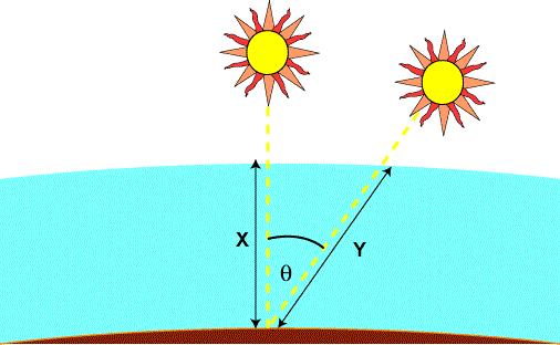
Figure 2. Schematic of air mass definition
The above calculation for air mass assumes that the atmosphere is a flat horizontal layer, but because of the curvature of the atmosphere, the air mass is not quite equal to the atmospheric path length when the sun is close to the horizon. However, it is reasonably accurate for values of zenith angel up to around 75°. At sunrise, the angle of the sun from the vertical position is 90° and the air mass is infinite, whereas the path length clearly is not. An equation which incorporates the curvature of the earth is:
\[\mathrm{AM} = \frac{1}{\cos(\theta)+0.50572(96.07995-\theta)^{-1.6364}}\]AM0, meaning “zero atmospheres”, is the spectrum outside the atmosphere. Solar cells used for space power applications, like those on communications satellites, are generally characterized using AM0.
AM1.5, corresponding to a solar zenith angle of 48.2°, was chosen as the ‘standard’ for terrestrial solar cell testing because it is a good representation of the yearly average irradiance in the temperate latitudes where there are many large population centres. The latest AM1.5 standards pertaining to photovoltaic applications are the ASTM G-173 and IEC 60904.
- AM1.5D: The direct radiation of the test plane when sunlight passes through 1.5 times thickness of the atmosphere at an angle of θ=48.2°. It is defined for solar concentrator work. It includes the the direct beam from the sun plus the circumsolar component in a disk 2.5 degrees around the sun. The direct plus circumsolar spectrum has an integrated power density of 900 W/m$^2$.
- AM1.5G: The global radiation of the test plane when sunlight passes through 1.5 times thickness of the atmosphere at an angle of θ=48.2°. The sum of the direct and diffuse radiation. It is designed for flat plate modules and has an integrated power of 1000 W/m$^2$ (100 mW/cm$^2$).
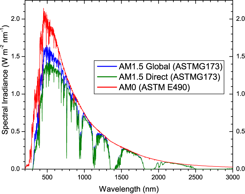
Figure 3. Reference solar spectral irradiances (ASTM)
The difference between AM 1.5G and AM1.5D: Solar radiation refers to the electromagnetic waves and particle streams emitted by the sun into space. The solar radiation energy received by earth is only one-twentieth billionth of the total solar radiation. Common solar radiation nouns are:
- Direct: When sunlight passes through the atmosphere, part of it reaches the ground without changing its radiation direction.
- Diffuse: Another portion of solar radiation that changes direction after being reflected and scattered by the atmosphere.
- Global: The sum of the direct and diffuse solar radiation reaching the ground after the weakening of the atmosphere.
- The relationship between Direct/Diffuse/Global is as the formula:
Reference:
- https://en.wikipedia.org/wiki/Air_mass_(solar_energy)
- https://www.ossila.com/en-jp/pages/standard-solar-spectrum
- https://www.pveducation.org/pvcdrom/appendices/standard-solar-spectra
- https://globalsolaratlas.info/download/world
- https://www.pveducation.org/pvcdrom/properties-of-sunlight/air-mass
- https://enlitechnology.com/zh-hans/blog/pv/ss-x-solar-simulatior/solar-simulator-01/